
The problem
There may be occasions when you have a microcontroller that does not have enough GPIO pins for a circuit! Your circuit may require a large number of switches or LEDs, which would use up lots of GPIO pins. It’s likely that you will need some of the GPIO pins for other parts of your circuit. Do you really want to use so many on just the switches or LEDs? Fortunately, there is a way that you can increase the number of GPIO pins available, by using a shift register.
The solution
Shift registers have different modes of operation but there are two that we are interested in – PISO and SIPO. If we need to increase the number of inputs, then we use a parallel-in serial-out (PISO) shift register. If we need to increase the number of outputs, then we use a serial-in parallel-out (SIPO) shift register. Both types of register convert data between serial and parallel. SIPO takes serial data and converts it into parallel data. PISO takes parallel data and converts it into serial data.
For this project I will be building four circuits. Two will be to increase the number of inputs and two to increase the number of outputs. In all of these circuits the shift register will use 4 GPIO pins and provide 8 INPUTS or OUTPUTS. There will be four circuits because I want to demonstrate how to achieve our goal with both TTL and CMOS SIPO and PISO shift registers.
PISO – TTL 74165
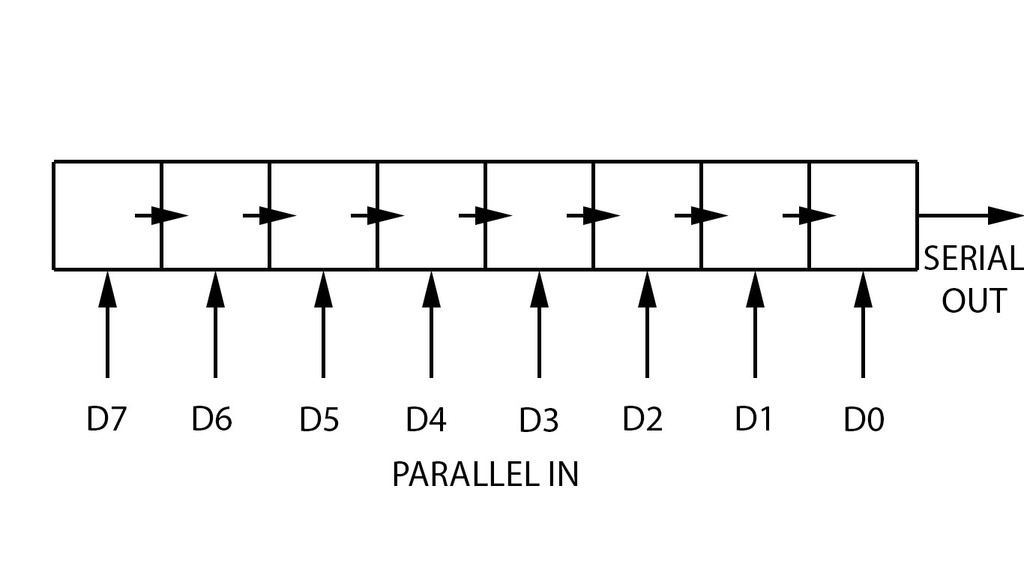
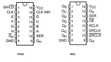
First, I will build a circuit using a PISO shift register, to increase the number of inputs. I will be using a 74165, which is an 8-bit shift register, which you load in your data in parallel and output in serial. By connecting the serial output to the input of a GPIO pin of an Arduino, we have increased the number of inputs available. The 74165 has used 4 GPIO pins and created 8 inputs, meaning that we have increased the number of inputs available by 4.
This shift register is 8-bit, which means that we can have 8 inputs but if we needed more, this is possible by chaining shift registers together! Not only does this further increase the number of inputs, because of the way that they are chained we still only use a total number of 4 GPIO pins! Therefore, with another 74165 chained to our first one, we have used 4 GPIO pins and we have 16 inputs available, therefore gaining 12 extra inputs!
CLOCK, DATA & LATCH
For a shift register to operate correctly, you need to understand the CLOCK, DATA and LATCH pins.
CLOCK
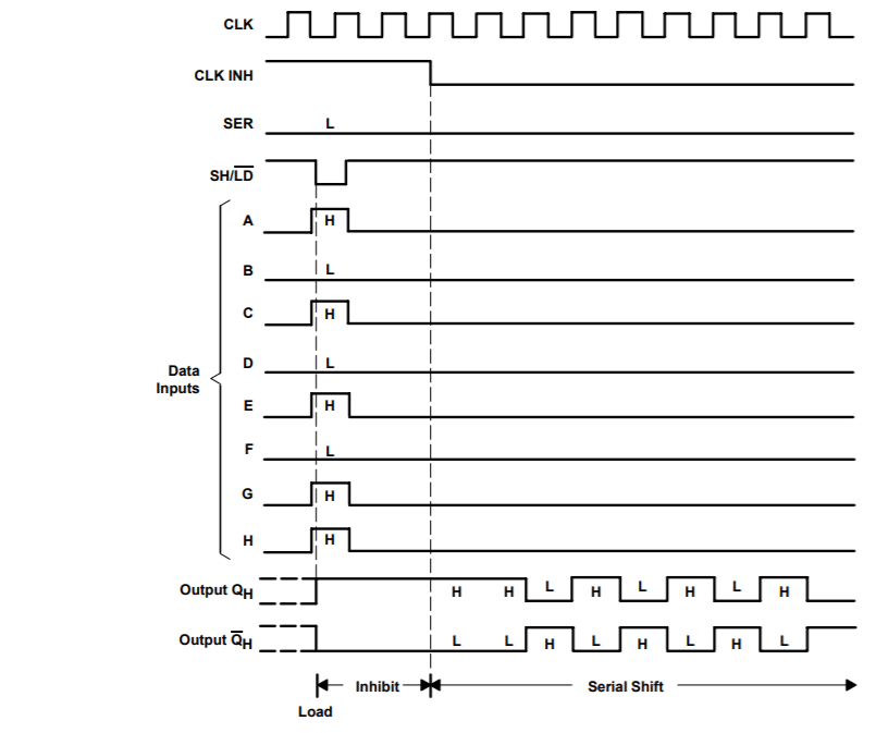
The 74165 is clock-driven. This means that we need a HIGH and RISING EDGE clock pulse to shift bits into the register.
DATA
The data pins are where we send our parallel data.
LATCH
When this pin is HIGH the contents of the register is copied into storage, making it available at the OUTPUT.
TOP TIP
There is actually a 4th pin that needs to be addressed for the 74165 to work correctly, CLK INH (pin 15). CLK INH needs to brought LOW to allow the data to be clocked. However, since there is no situation where we want to stop data being clocked, CLK INH can be permanently connected to ground. This allows us to use 3 GPIO pins, instead of 4! Also, no code needs to be written to control it.
THE CIRCUIT

THE CODE
First I declare and assign 6 variables.
int i = 0;         // variable for reading 8-bit data
int PinState = 0;   //read the state of the SO pin
int Parallel_data = 0; //To store parallel data
int SO = 2; // SO-Serial output (Pin 9) of 74165 is connected to the digital pin 2 of Arduino UNO.
int SH_LD = 3; // SH/LD (Pin 1) of 74165 is connected to the digital pin 3 of Arduino UNO.
int CLK = 4; // CLK (Pin 2) of 74165 is connected to the digital pin 4 of Arduino UNO.
In the void setup() function the serial monitor is initialised and setup. pinMode is used to set the latch pin to an output, clock to an output and serial out to an input.
  // initialise serial communication at 9600 bits per second
  Serial.begin(9600);
  // initialise the SH_LD & CLK pin as an output
  pinMode(SH_LD, OUTPUT);
  pinMode(CLK, OUTPUT);
  // initialise the SO-Serial output pin as an input
  pinMode(SO, INPUT);
In the void loop() function the latch and the clock is set low, followed by a 5 ms delay.
digitalWrite(CLK, LOW);
  // Parallel data that will be entered through D0 - D7 Pins of 74165
  digitalWrite(SH_LD, LOW);
  delay(5);
The latch pin is then set high.
digitalWrite(SH_LD, HIGH);Text is then sent to the serial monitor.
Serial.print("serial output: ");Then there is a for loop that checks the state of the serial ouput and sets the clock low and high when needed.
for(i=0; i<8; i++)
    {
        PinState = digitalRead(SO); // read the state of the SO:
       digitalWrite(CLK, LOW);
        delay(1);
        digitalWrite(CLK, HIGH);
        delay(1);
        Serial.print(PinState); //Send out one by one parallel data to serial monitor
        Parallel_data = (Parallel_data<<1)|PinState; //Store the value in Parallel_data
    }
A new line is created and a delay of 1s. The loop is then repeated.
Serial.println();
   delay(1000);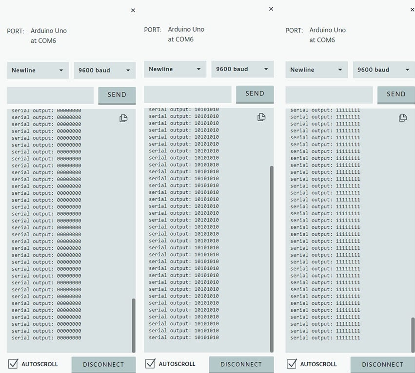
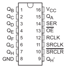
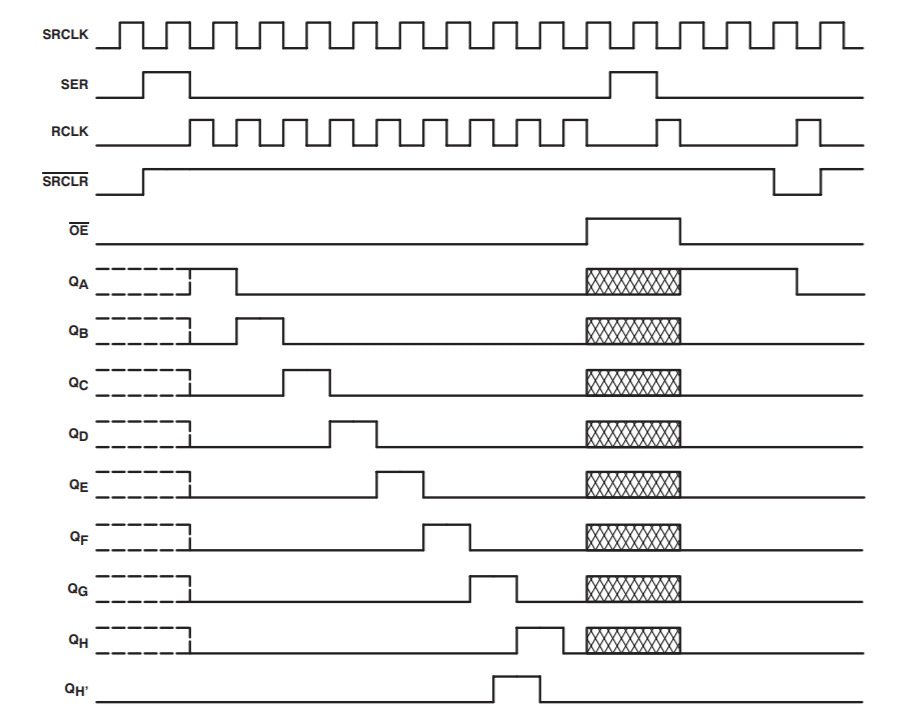
Next, I will build a circuit using a SIPO shift register, to increase the number of outputs to an Arduino. There are a number of SIPO shift register available, I am using the 74595. The 74595 is an 8-bit register which you load your data in serial and output in parallel. By connecting an output of a GIPO pin of the Arduino to the serial input of the 74595 we have increased the number of outputs available. 8-bits means that we can have 8 outputs but if we needed more, this is possible by chaining shift register together!
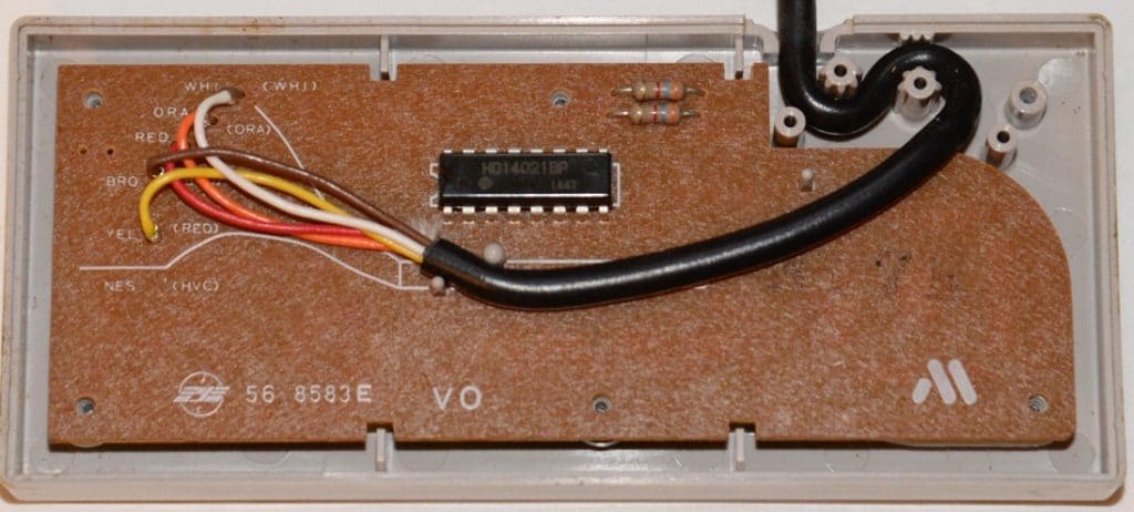
Controllers for games consoles are a good example of shift registers in real world use. They use PISO shift registers to reduce the number of wires needed in the controller lead. A really good example is the NES, which uses a 4021. The NES controller has 8 buttons but the controller uses 5 connections: +V, ground, latch, data and clock. By using a shift register the engineers were able to use 1 connection (data) instead of 8 if the buttons were connected individually.
Sticking with the gaming world, SIPO shift registers are also used inside games consoles and arcade systems. The 74595 was used in the Atari system 1.
FURTHER READING
If you would like to learn even more about shift registers, including 2 other types (SISO and PIPO), then take a look at this lesson: Shift Registers
If you would like to learn more about the Arduino GPIO pins, including their differences, then have a look at this lesson: GPIO pins