
OBJECTIVE
A range finder is a device that is used to find the distance between two points, using a technique known as ranging. In this project we will design and build a range finder that can measure how far away an object is, from 2 cm to 4 m (0.79 in to 13.12 ft). The range finder will display the results in both centimetres and inches.
THE METHOD
We will use an ultrasonic sound sensor to provide the data necessary to calculate the distance. The ultrasonic sensor contains two transducers. One is like a speaker, sending out pulses of sounds and the other is like a microphone, responding to the sound received. The longer it takes for the sound to come back, the further away the object is.
THE SCIENCE
Ultrasonic sound is defined by the American Standards Institute as sound at frequencies greater than 20 kHz (which is the typical upper hearing limit of humans).
To use ultrasonic sound to calculate distance we need to know the speed that the sound will be travelling at and the time for the sound to get to the object, which we can express as distance = speed x time. The speed of sound in air is a constant, 343 m/s (1,125 ft/s). Because sound waves are mechanical, they travel differently through different mediums. We are interested in air, if we were developing a device to measure how far away objects were in water, our constant would be different. The time component will be calculated by the amount of time taken from the pulses leaving the transmitting transducer and being received by the receiving transducer, divided by 2! We divide by 2 because we need the time taken for the signal to reach the object. Therefore, in our code we will use a modification of the distance formula, distance = speed x (time/2).
The ultrasonic sensor that we will use contains two transducers. A transducer is a device that converts energy from one form to another, in this case, mechanical and electrical energy. One of them transmits a 40 kHz signal and the other receives an echo of this signal. The longer it takes to receive the echo, the further away the object is. When there is no object in front, or in range, the receiver will not detect an echo.
THE HARDWARE
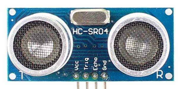
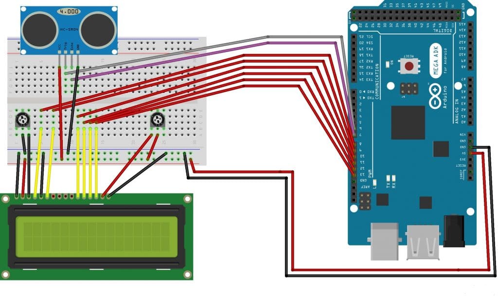
The ultrasonic sensor that I will be using is the HC-SR04 (Figure.1 and figure.2). The HC-SR04 has 4 pins. VCC, which connects to the 5v. Trig, which is the input to the device. Echo, which is the output to the device. GND, which connects to ground.
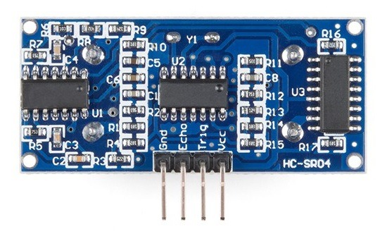
On the front there are 2 metal cylinders, which are the transducers. On the back of the board, there are 3 ICs. There is a MAX3232, which controls the transmitting transducer. There is also an LM324, which is a quad op-amp, which amplifies the signal from the receiving transducer so that it is strong enough to use. There is also an 8-bit microprocessor.
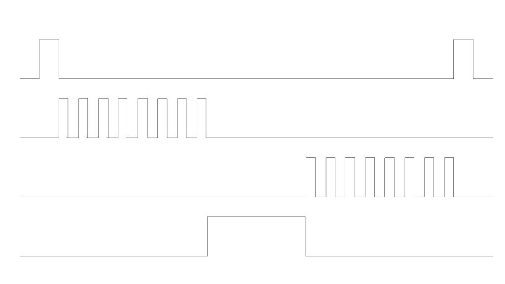
We need to send a 5v 10μs pulse to the trig pin. The HC-SR04 will then transmit 8 ultrasonic pulses at 40 kHz. The echo pin outputs a pulse of 150μs to 25ms. The pulse width of the echo pulse is used to calculate the distance. The echo pulse will timeout if no object is detected after 38ms.
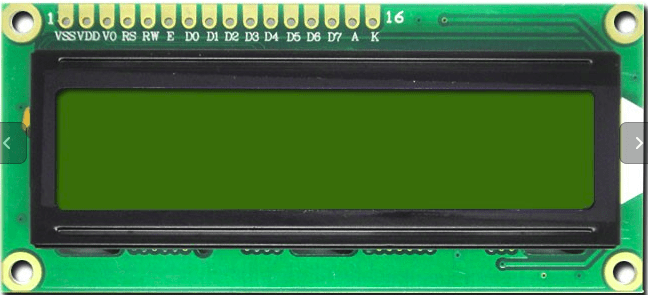
The LCD that I will be using is the LCM1602C. This is a 16 x 2 LCD, which means that it has 2 rows of 16 and can therefore display a maximum of 32 characters. The LCD has 16 pins, and can be run in 4-bit and 8-bit mode. We will use it in 4-bit mode, using D4-D7 to send the data from our Arduino to our LCD. We will use this to display the distance in both centimetres and inches. (Figure.3). You can use any LCD that is compatible with the HD44780 driver.
THE CIRCUIT
THE CODE
The first thing that we do is to include the LiquidCrystalLibrary.
#include <LiquidCrystal.h>Next we define which pins we will use for the trigPin and the echoPin.
#define trigPin 2
#define echoPin 3
Next we use LiquidCrystal lcd() to set the 6 pins that we will connect to the LCD.
LiquidCrystal lcd(8, 9, 10, 11, 12, 13);In our void setup() we will use the serial monitor and set the baud rate at 9600. Then we use pinMode to set the trigPin as an OUTPUT and echoPin as an INPUT.
void setup() {
  Serial.begin (9600);
  pinMode(trigPin, OUTPUT);
  pinMode(echoPin, INPUT);
}
In our void loop() we will define 2 float variables: duration and distance. We are using the type of float because we want to be able to display our distance to two decimal places. We then use digitalWrite to set the trigPin to LOW and use delayMicroseconds to set a delay of 2 µs. This is done to make sure that the trigPin is not HIGH when we start our program. The duration of the delay isn’t important, just that the trigPin is not HIGH.
We then set trigPin to HIGH, which will make the transmitting transducer send 8 40 kHz pulses. To work this needs to last for 10 µs, so delayMicroseconds is used again to achieve our delay. We then set trigPin to LOW as we need to have the transmission end after the 10 µs have elapsed.
We now need to listen for an echo, so we use pulseIn to set echoPin HIGH. We allocate the result of this to our duration variable. We then allocate to our distance variable the results of what is stored in our duration variable, divided by 2, multiplied by the speed of sound.
We then use lcd.setCursor to start the cursor in the top left-hand corner. We then use lcd.print to print the value stored in the distance variable to LCD, followed by cm. We then implement a 1000 µs delay, followed by another 1000 µs delay. We then use lcd.clear to clear what’s on the LCD.
void loop() {
  float duration, distance;
  digitalWrite(trigPin, LOW);
  delayMicroseconds(2);

  digitalWrite(trigPin, HIGH);
  delayMicroseconds(10);
  digitalWrite(trigPin, LOW);

  duration = pulseIn(echoPin, HIGH);
  distance = (duration / 2) * 0.0343;

  lcd.setCursor(0, 0);
    lcd.print(distance);
    lcd.print("cm ");
    lcd.print(distance / 2.54);
    lcd.print("in");
    delay(500);

  delay(500);
  lcd.clear();
}
Define the distance variable as the duration multiplied by the speed of sound. However, we need to make modifications to this calculation. As mentioned previously, we need to divide the duration by 2. Also, we will convert our measurement of speed in m/s to cm/µs.
cm to m: 343 / 100 = 3.43
ms to µs 3.43 / 1,000 = 0.0343 (0.0343 cm/µs)
m/s to cm/µs
We use the Serial.print command to print to the serial monitor the distance calculated. We then create a delay of 500 ms to hold the information on the serial monitor.
IMPROVEMENTS
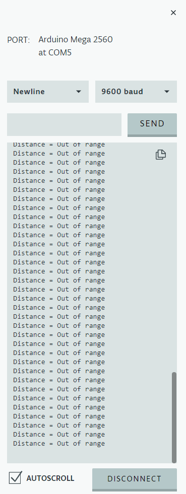
One thing we could do to improve our range finder is to provide a message if the object is out of range. The HC-SR04 can detect objects at distances between 2cm and 4m. Therefore we could provide a message if the object is less than 2cm or more than 4m away. We can do this by writing an if statement:
if (distance > 400 || distance < 2){
    lcd.setCursor(0, 0);
    lcd.print(" THE OBJECT IS");
    lcd.setCursor(0, 1);
    lcd.print("  OUT OF RANGE");
    delay(1000);
  } else {
    lcd.setCursor(0, 0);
    lcd.print("THE DISTANCE IS");
    lcd.setCursor(0, 1);
    lcd.print(distance);
    lcd.print("cm ");
    lcd.print("   ");
    lcd.print(distance / 2.54);
    lcd.print("in");
    delay(1000);
  }
A further two improvements can be made by detecting and factoring in 2 environmental factors that affect the speed of sound in air, temperature and humidity. Our results have been based on our calculations of the speed of sound being 343 m/s (1,125 ft/s). This is true, at a temperature of 20°C(68 ° F). The speed of sound changes with temperature changes. Therefore, if we measured the temperature at each reading, we could factor this in to improve the accuracy.
Humidity also has a small effect on the speed of sound. As the humidity rises, the speed of sound increases. This is because air contains mainly nitrogen and oxygen. As the humidity increases, these elements are replaced by water vapour, which is lighter.
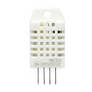
We will add a combined temperature and humidity sensor, the DHT22. This requires an operating voltage of between 3.3 and 6v, so we can use either the 3.3v or 5v connections on the Arduino. The DHT22 can work in 0 – 100% humidity, which covers all humidity values that we would come across. The DHT22 can work in a temperature range of -40 to 80°C, which covers all temperature values that we are likely to ever come across.
FINAL CODE
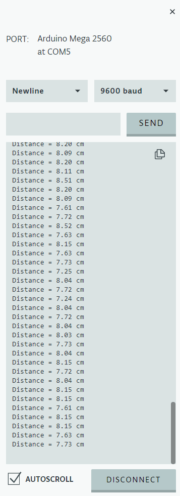
THE RESULT
LIMITATIONS
One of the limitations of a range finder that uses ultrasonic sound is that accurate results will not be given when the object does not reflect sound well, as it will absorb some of the sound. I hypothesize that sponge would be such a material and will therefore carry out some tests on sponge. With less ultrasonic sound waves bouncing back I would expect to either get a false result or a reading of OBJECT OUT OF RANGE. I tested this with a piece of sponge and I no longer had reliable results at any distance. Often I received an OBJECT OUT OF RANGE which suggests that most of the waves are not being reflected, instead they are being absorbed.
I also hypothesize that even though there is an operational range of 2cm – 4m, the reality is that there is a portion of that range that will not provide as accurate readings. My thinking is that as sound waves get further away from their point of origin, the waves get wider and weaker. There needs to be enough energy in the waves for the echo to be accurate.
PRACTICAL APPLICATIONS
A great use of a range finder is for robots and cars that need to detect objects nearby.