
THE PROBLEM
Switch bounce can be problematic in some circuits if no action is taken to address it. We live in an analogue world but often want to provide a digital input to circuits, switch bounce is one of the issues that arise from this. Essentially the job of a switch is to transition between an open-circuit and a closed-circuit.
When you press a button you may think that contact between its terminals is only made once but this is not the case! Switches suffer from ‘bounce’. Switch bounce describes how the contacts of switches make contact multiple times, even though the switch has only been pressed once! Think of a ball. When you drop it to the ground, it does not hit the floor once and stay there! Instead, it bounces a number of times before stopping! Switches bounce because of their mechanical nature. The materials that switch contacts are made from are ‘springy’ and not perfectly flat, so they do not make a ‘clean’ contact. Rather, they ‘bounce’ multiple times, causing multiple connections and disconnections from a single press.
In many situations, switch bounce is not a problem, such as turning on a light in your home. However, there are many cases where this effect, which is imperceivable to humans, would cause problems! When you press a button on a controller of a games console, multiple pulses from one press could be enough to make you lose a game! There are many cases where we need to ensure that one press means one pulse and not one press means a circuit interpreting switch bounce as multiple pulses!
THE SOLUTION
Fortunately, there are a number of methods that we can employ to circumvent this problem. These solutions are known as ‘debouncing‘. We can split these debouncing techniques into hardware and software solutions. Regardless of which method we choose, our goal is to make each press of a switch clean, so that one press causes one pulse to be registered.
Hardware solutions
There are multiple approaches to using hardware to debounce a signal, we will be taking a look at two of these: the low-pass filter and the SR flip-flop.
Low-pass filter
The switch bouncing is relatively high frequency and therefore one approach to remove the bouncing is to use a filter which is designed to only remove high frequencies.
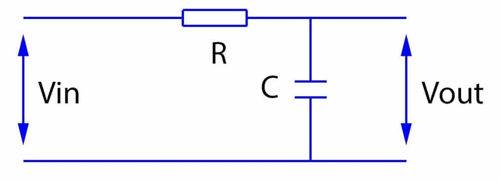
Filters are a group of circuits that are used to remove a range of frequencies from a signal. The type of filter that we need is a low-pass filter. A low-pass filter only allows low frequencies, from 0Hz to a cut-off frequency to pass through it. The frequencies above the cut-off (which will include our bouncing) will not pass through. The type of low-pass filter that we will use is an RC low-pass filter. This is a passive (contains no amplifying components) filter made from a single resistor and capacitor.
Figure 1 shows the RC filter that I will build. The resistor is in series with the load and the capacitor is in parallel with the load. To understand how an RC low-pass filter works, you need to understand capacitive reactance. Capacitive reactance is a measure of a capacitor’s opposition to AC. Capacitive reactance is measured in Ohms and is frequency dependent. Therefore, as the frequency of our input changes, so will the capacitor’s capacitive reactance. The resistance of a resistor does not change with frequency. Therefore, as the frequency of our input changes, the resistor’s resistance will stay the same. Reactance is inversely proportional to the capacitance of the capacitor – capacitive reactance decreases as the capacitance increases. Since the capacitor is in parallel to the load, frequencies above the cut-off never make it to the load as the capacitor is a lower path of resistance (lower capacitive reactance). Conversely, when frequencies below the cut-off are present, they do make it to the load, since the capacitor is a greater path of resistance. Therefore, any low frequencies (below the cut-off) pass through the filter because the capacitive reactance will be high. Any high frequencies (above the cut-off) do not pass through the filter because the capacitive reactance will be low.
Ideal vs reality
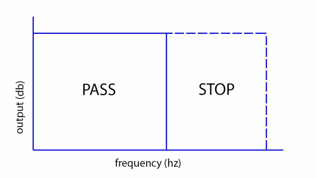
Figure 2 shows what the frequency response from a perfect low-pass filter looks like. An ideal low-pass filter would have a sudden drop-off when the frequencies transition from below cut-off to cut-off.
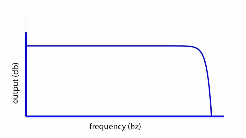
In reality, this would be impossible to achieve. Figure 3 shows what the frequency response from a low-pass filter is more likely to be. Instead of a ‘step’, we have a slope! There are limitations to this iteration of an RC filter but for switch bouncing, as long as the bouncing occurs in the cut-off portion, then it will suit our purpose.
SR flip-flop
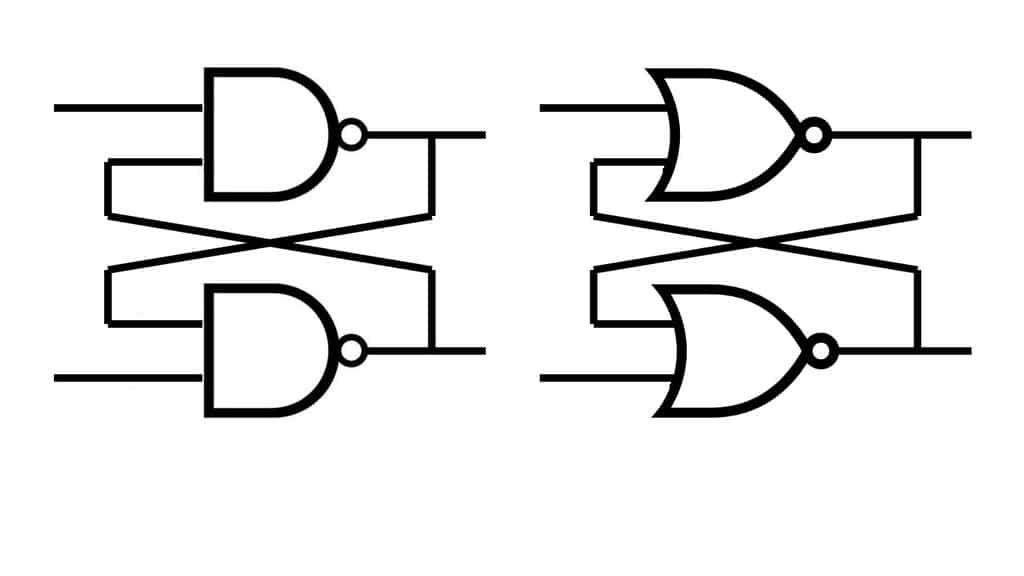
The SR flip-flop is a form of sequential logic that is often used as a form of memory. Sequential logic takes into account their previous input state as well as the present state. An SR flip-flop can be built by cross-coupling either 2 NAND or 2 NOR gates, as shown in FIgure 1.
Table 1 shows a truth table for our SR flip-flop. There are two scenarios, where S and R are at 0 and Q is at 1 and where S and R are at 0 that normally have to be considered because they are unpredictable! However, because I have used a pull-up resistor on each input, this will never happen, as at least one of the inputs will always be at 1 and therefore at least one of the inputs will always be at 0! Therefore Table 1 include the combinations that we are interested in.
| S | R | Q | |
| SET | 1 | 0 | 0 |
| RESET | 0 | 1 | 1 |
Software solutions
Software can also be used to debounce a switch. This has the advantage of saving space and money! One solution is to add a delay after the switch is first pressed. There are situations where this can work, however, when using a microcontroller this will often not be a good solution. This is because the microcontroller is occupied while it waits for the delay to end. A much better solution is to use an interrupt.